Tool reference
Every Forge action includes contextual guidance in the app. This reference brings together the same practical information: what the action does, when to reach for it, and the important constraint to remember.
Native for macOS and iPadOS. Every tool documented here is part of the Forge workflow on both platforms.
Selection matters. If an action is unavailable or has no effect, switch to the component type named in its notes and make the required selection first.
Find the right tool
What do you want to do? connects common tasks to tools and compares similar operations.
New to Forge? Use Learn by example for guided projects, selection basics, and an explanation of Preview, Apply, Done, and Undo.
The selection-mode lines below list supported modes; a valid selection is still required. Read each tool's notes for restrictions such as “exactly two vertices” or “one quad face.”
Trying to center two objects? Start with Center and align objects. Transform → Detail → Position provides numeric object placement. Align to Face is a Face-mode attachment tool.
The symbols below are the same SF Symbols used by the Apple app. In the right-hand Actions panel, cycle the header layout button until names and descriptions are visible. Select an object or component first: available actions depend on Object, Vertex, Edge, or Face mode.
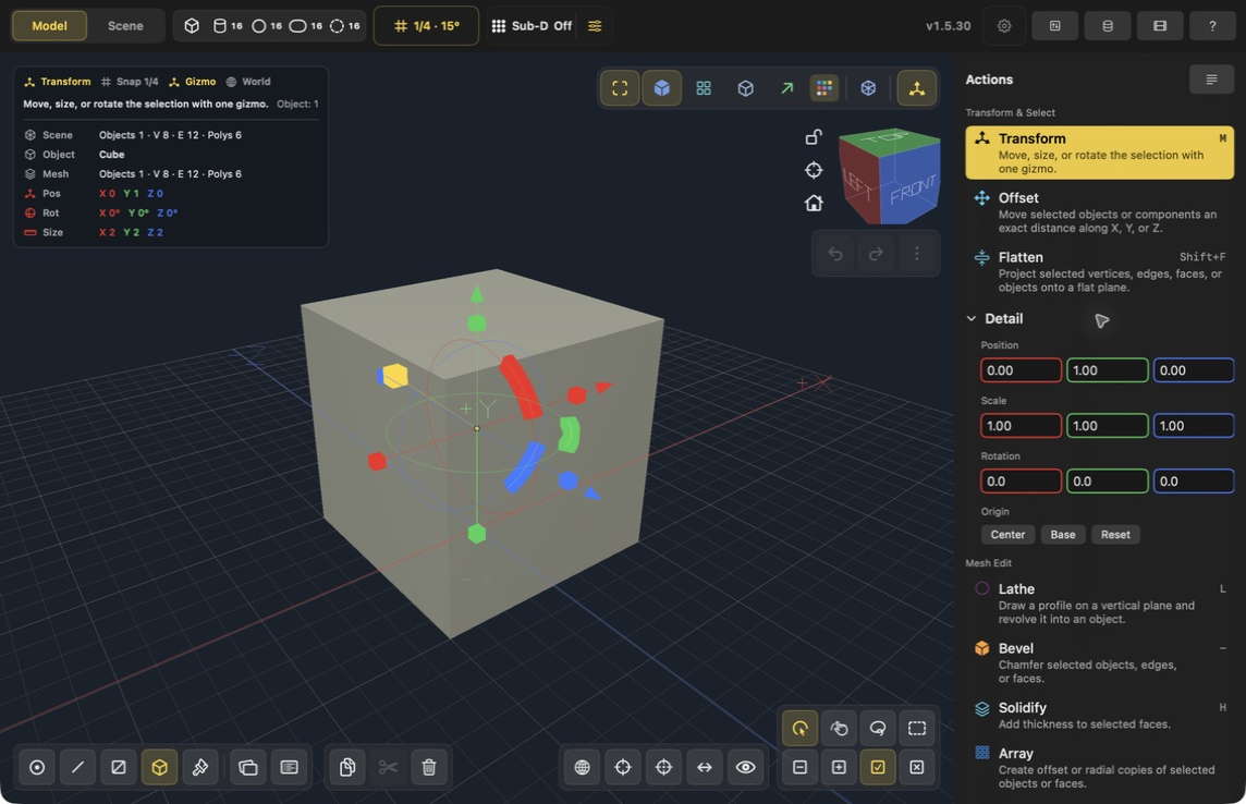
Mac SwiftUI interface, v1.5.30. Transform is highlighted in the right Actions panel. Expand Detail below the transform tools for exact values; X, Y, Z fields run left to right. Click a screenshot to inspect it at full size.
Transform and shape
Transform

Selection modes: Object, Vertex, Edge, Face.
Move, size, or rotate selected objects, or move selected components.
Use it for: Use Transform as the default modeling gizmo: drag arrows to move, side handles to size object selections, and rotation handles to rotate object selections.
Notes: Choose World, Local, Selection, or View axes. Selection follows the active component, while View keeps its horizontal and vertical axes aligned with the screen.
Find it: Select an object in Object mode, then choose Transform in the right Actions panel (Mac shortcut M). Expand Detail for Position, Scale, and Rotation. Enter a Position value and press Return to commit it; this numeric edit does not have a separate Apply step.
Centering objects: Follow the illustrated alignment steps. Origin → Center changes the pivot without moving the mesh. The transform-center menu changes the gizmo pivot; it does not align objects.
Example: Move a wheel into place in Object mode; switch to Face mode to move only a selected surface. For exact center alignment, follow Center and align objects.
Size

Resize a selected object with the Transform gizmo's size handles, or use Transform → Detail → Scale for exact factors. Scale 2 doubles the corresponding original dimension.
Find it: In the current modeling Actions panel, use Transform. Size is not a separate action there. See the wall setup example.
Rotate

Rotate selected objects with Transform's rotation handles, or enter angles in Transform → Detail → Rotation. The axis orientation menu changes how the gizmo is oriented.
Find it: In the current modeling Actions panel, use Transform. Rotate is not a separate action there. Use the Rotation fields for exact angles and press Return after editing.
Offset

Selection modes: Object, Vertex, Edge, Face.
Move the current selection by an exact signed distance on one world axis.
Use it for: Select one or more objects, vertices, edges, or faces, choose X, Y, or Z, enter the distance in the current project unit, then apply Offset.
Notes: Positive and negative values move in opposite directions. Multi-object and multi-component selections keep their relative spacing, and typed values remain exact even when slider movement follows the grid step.
Example: Raise a selected shelf by 0.5 on world Y without changing its X or Z position. With several objects selected, Offset moves the group of selected parts together; it does not close the gaps between them.
Flatten

Selection modes: Object, Vertex, Edge, Face.
Project the current selection onto a flat plane.
Use it for: Use Flatten to clean warped polygons, align edge loops, or make selected vertices share an X, Y, Z, or calculated best-fit plane.
Notes: Angle mode uses a best-fit plane through the selected world-space points. Axis modes flatten to the selection center on that world axis.
Example: Select vertices on a warped tabletop and choose the Y axis to bring them to one height. Inspect the preview before applying so you do not flatten the entire table by mistake.
Relax

Selection modes: Vertex, Face.
Even out selected mesh vertices with one conservative smoothing pass.
Use it for: Select distorted vertices or faces, then use Relax to move the interior vertices toward the average of their connected neighbors.
Notes: Boundary vertices remain fixed and the command is undoable. Repeat deliberately for stronger smoothing.
Example: Select a lumpy patch of vertices on a curved prop and apply one pass. Compare the silhouette before repeating; the operation changes vertex positions, not the number of faces.
Circlify

Selection modes: Vertex, Edge, Face.
Turn a selected loop or face-region boundary into a circle.
Use it for: Select a closed vertex or edge loop, or a connected face region, then adjust Influence and apply Circlify. Enable Regular Spacing for evenly distributed vertices.
Notes: Face selections use their outer boundary. Branched or open selections are left unchanged; Preserve Surface projects the result back onto the original mesh.
Example: Select the closed edge boundary of an uneven opening to make it round. Regular Spacing evens out the points; it is useful when the ring should also have evenly spaced segments.
Push/Pull

Selection modes: Face.
Move selected faces along their face normal.
Use it for: Use Push/Pull for architectural massing: raise panels, recess walls, or pull a face outward without creating a separate object.
Notes: The tool previews the offset. Apply from the sidebar or drag the normal handle.
Example: Move the top face of an existing block to adjust its height. Use Extrude when you want an additional connected section with new side faces, as in the raised-panel lesson.
Extrude

Selection modes: Edge, Face.
Create new connected geometry from selected faces.
Use it for: Use Extrude when you need a new volume that remains attached, like a ledge, pillar, handle, or branch.
Notes: Apply Extrude commits one extrusion and keeps Extrude active, so repeated clicks continue from the newly selected faces.
Example: Make a raised square panel: inset the top of a box, keep the inner face selected, then extrude it by 0.75. Follow the screenshot walkthrough. Apply commits; Done exits. Another Apply continues extruding the new face.
Inset

Selection modes: Face.
Create a smaller region inside selected faces.
Use it for: Use Inset before pushing a panel inward, making frames, lips, borders, doors, windows, or recessed details.
Notes: Use Inset per face for separate panels, or turn it off to inset connected coplanar faces as one region.
Example: Make a frame on a box face with Amount 0.25, then extrude the inner face. See the Inset controls and result. Inset changes the surface border; it does not by itself raise the panel.
Arc

Selection modes: Face.
Round a selected quad face into a segmented arch.
Use it for: Use Arc for arched doorways, rounded tops, and simple curved silhouettes while staying low-poly.
Notes: Works best on a single quad face. Segment and height controls shape the curve.
Example: Select one quad face for the top of a doorway, then preview a segmented arch. Increase the segment count only enough to describe the curve you need.
Knife

Selection modes: Face.
Draw a knife polygon on the selected face.
Use it for: Use Knife to place windows, holes, panels, and custom face regions before using Cut Through, Push/Pull, or Inset.
Commit controls: Apply Cut commits the drawn cut and returns to Transform. Undo Point removes the latest point; Cancel Cut abandons the cut. For a rectangular opening, follow Make a window.
Notes: Knife can begin on any visible face in a multi-face selection, snaps to nearby vertices, and keeps grid-snapped points on rotated face planes. Two points create a straight split.
Example: Draw a smaller window-shaped region on a wall face, commit the cut, and select that new region before using Cut Through. Drawing cut lines alone does not make a hole through the wall.
Lathe

Selection modes: Object.
Revolve a drawn profile into a radial object.
Use it for: Use Lathe for barrels, columns, bowls, vases, wheels, and other shapes that come from a side profile.
Notes: Draw points on the vertical plane. Segments, subdivisions, and cap toggles control the generated mesh.
Example: Draw one side of a vase profile on the vertical plane, then revolve it. The profile describes the side silhouette; segment count determines the number of divisions around the vase.
Align to Face

Selection modes: Face.
Attach a selected mesh region to another face using the active face as the source.
Find it: Switch to Face mode, select the source faces, then choose Align to Face in the Actions panel. It is unavailable in Object mode. To center whole objects, use Position instead.
Use it for: Select the faces to move, make the attachment face active last, start Align to Face, then pick the destination face in the viewport.
Notes: The source face is placed against the destination face with opposing normals. The selected region moves rigidly without changing topology.
Example: Attach a selected mounting face to a support face. Select the moving region, make its attachment face active last, start the tool, then click the support face. To center entire objects instead, use Position.
Cut Through

Selection modes: Face.
Turn a selected cut face into a tunnel through the object.
Use it for: Use Cut Through after Knife to make real openings like windows, vents, archways, and intersecting passages.
Notes: The command builds tunnel side faces and can merge with existing through-cuts. It runs directly, without another Apply step. See the before/after window example.
Example: After Knife creates a window region on a solid wall, select that region and use Cut Through to connect an opening through the wall. Use Delete only when removing a face without building tunnel walls is the intended result.
Bevel

Selection modes: Object, Edge, Face.
Chamfer selected objects, edges, or face borders.
Use it for: Use Bevel on selected faces to round the border of the face island, or on selected edges and objects for direct edge chamfers.
Notes: Use low segment counts for interactive work. Preview shows the affected chamfer area.
Example: Round a default cube with Amount 0.20 and Segments 3. Compare the preview with the committed wireframe. One segment makes a flat chamfer; more segments add strips around the curve.
Solidify

Selection modes: Object, Face.
Add thickness to selected faces.
Use it for: Use Solidify to turn planes, panels, roofs, and shell surfaces into real volume.
Notes: Selected faces are replaced by an offset surface plus clean side faces.
Example: Give a thin roof panel a wall thickness. Check the offset direction in the preview so the new surface extends toward the intended side.
Subdivide

Selection modes: Object, Face.
Split selected faces into smaller faces.
Use it for: Use Subdivide when you need more editable regions before painting, cutting, beveling, or shaping local detail.
Notes: In component mode, child faces remain selected so you can continue editing immediately. In Object mode, every face of each selected object is subdivided and the objects remain selected. This is destructive and separate from Sub-D preview.
Example: Split a large face into smaller editable regions before adding local detail. Use Sub-D if the goal is a reversible smooth preview rather than more permanent mesh faces.
Sub-D

Selection modes: Object, Vertex, Edge, Face, Paint, Scene.
Preview a smooth subdivision surface while keeping the original object editable.
Use it for: Select one or more objects, or keep editing vertices, edges, or faces, then use the Sub-D popover to choose Off or preview levels one through three.
Notes: Sub-D preview can be toggled while editing the original cage. Freeze is still a separate object-mode step for turning the smoothed result into real mesh faces.
Example: Preview a smoother prop at level 1, compare with level 2, and choose Off to return to the original cage appearance. Freeze is only needed when you want to bake the preview.
Freeze Sub-D

Selection modes: Object, Scene.
Bake the current Sub-D preview into ordinary editable mesh geometry.
Use it for: Use Freeze Sub-D after the preview level looks right and before exporting or doing detailed mesh edits on the smoothed result.
Notes: Freeze is undoable, but the generated mesh can be much denser than the original cage.
Example: Bake the approved smooth form before editing its generated vertices. Check the mesh density first: freezing can create many more faces than the starting model.
Ruler

Selection modes: Vertex.
Measure the point-to-point distance between two selected vertices.
Use it for: Switch to vertex mode, select exactly two vertices, then click Ruler to show their world-space distance.
Notes: The viewport HUD formats the measurement using the current document's Units setting.
Example: Select exactly two vertices at opposite ends of a feature and use Ruler to check its point-to-point distance. Use the document Units setting to interpret the displayed measurement.
Selection and visibility
Select Loop

Selection modes: Vertex, Edge, Face.
Extend two adjacent components into a loop.
Use it for: Select two neighboring vertices, edges, or faces, then use Select Loop before beveling, sliding, deleting, or transforming a continuous belt.
Notes: Most useful on quad-based topology. Face loops follow the strip through opposite quad edges.
Select Edge Ring

Selection modes: Edge.
Select opposite edges across a quad strip.
Use it for: Use Select Edge Ring to prepare a Loop Cut or to inspect evenly spaced structure through a mesh.
Notes: Works best on connected quad strips.
Select Boundary

Selection modes: Face.
Select the boundary around selected faces.
Use it for: Use Select Boundary before filling, beveling a face perimeter, or inspecting the outline of a region.
Notes: Face mode converts to edge selection around the selected region.
Example: Select a patch of faces on a panel, then convert the selection to the surrounding edges before working on its outline.
Select Connected

Selection modes: Vertex, Edge, Face.
Select the connected island for the current component type.
Use it for: Use Select Connected to grab one detached part of a mesh without manually picking every face or edge.
Notes: Works in vertex, edge, and face modes.
Example: Select one component of an isolated mesh island, then expand to the connected part rather than manually selecting each element.
Select Coplanar

Selection modes: Face.
Select faces on the same plane as the current face.
Use it for: Use Select Coplanar to grab flat walls, floors, caps, and panels for material assignment or cleanup.
Notes: The command compares face planes, so curved or angled surfaces are excluded.
Example: Select a face on a flat wall to gather other faces lying on its plane. Curved neighboring surfaces do not belong to the same plane.
Select Hard Edges

Selection modes: Edge.
Select edges between sharply angled faces.
Use it for: Use Select Hard Edges to find bevel candidates or check where the model has strong silhouette breaks.
Notes: Requires edge mode and visible mesh topology.
Select Open Edges

Selection modes: Edge.
Select naked boundary edges.
Use it for: Use Select Open Edges to find holes, unfinished surfaces, and areas that may need Fill Holes.
Notes: Open edges are also highlighted by mesh-health overlays.
Select UV Island
Expand the current selection to the complete seam-delimited UV island.
Use it for: Select a vertex, edge, or face in the island, then use Select UV Island before unwrapping, packing, moving, or rotating that chart.
Notes: The command selects every face in the UV island containing the current component selection and works from Vertex, Edge, or Face mode.
Grow Selection

Selection modes: Vertex, Edge, Face.
Expand the current component selection outward.
Use it for: Use Grow when your face, edge, or vertex selection is almost right and needs one more neighboring ring.
Notes: Face growth includes neighbors that meet along an edge or at a corner.
Example: Start with a few faces at the center of a detail and grow outward one step at a time. Check the highlighted boundary after each step.
Shrink Selection

Selection modes: Vertex, Edge, Face.
Contract the current component selection inward.
Use it for: Use Shrink to remove the outer border from a selected region before applying a command.
Notes: Works on component selections.
Example: Select a broad face patch, then shrink to remove its outer ring and work on the interior.
Hide Selected
Hide the current object or face selection without deleting it.
Use it for: Clear obstructing geometry from the viewport while editing interior or back-side details.
Notes: In Object mode it hides selected objects and clears their selection. In Face mode it hides selected faces. The command is undoable.
Hide Unselected
Isolate the current object or face selection by hiding everything else.
Use it for: Focus on one object hierarchy or a face region without changing the underlying scene.
Notes: Object mode keeps selected hierarchies together. Face mode isolates the selected faces on the active object.
Reveal All
Show all hidden objects or faces again.
Use it for: Restore the complete scene after a focused editing pass.
Notes: Use it from Object mode for scene objects or Face mode for hidden faces. Visibility changes are undoable.
Topology and repair
Split Edge

Selection modes: Edge.
Insert midpoint vertices on selected edges.
Use it for: Use Split Edge to add control points before filling, reshaping, or creating cleaner manual topology.
Notes: Works on edge selections and keeps the inserted vertices selected.
Merge

Selection modes: Vertex, Edge, Face.
Merge selected vertices, edges, or faces.
Use it for: Use Merge to collapse vertices, dissolve internal edges, or turn connected face groups into a larger n-gon.
Notes: The viewport previews mergeable selections before commit.
Connect

Selection modes: Vertex.
Connect two selected vertices with a new edge path.
Use it for: Use Connect in vertex mode to draw topology across one face or a simple strip of faces.
Notes: Connect needs exactly two vertices on the same object and refuses ambiguous paths.
Fill

Selection modes: Vertex, Edge.
Create a face from selected boundary vertices or edges.
Use it for: Use Fill after deleting faces, opening a mesh, or selecting one edge of an open boundary you want to cap.
Notes: When an open boundary edge is selected, Fill caps the whole boundary loop that contains it.
Bridge

Selection modes: Edge, Face.
Create bridge faces between two compatible selections.
Use it for: Use Bridge on two edges to patch a gap, or on two matching faces to turn them into a connected tunnel.
Notes: Face bridges need two selected faces with the same vertex count.
Example: Connect matching open borders to build a band of faces between two regions. Check that the chosen boundaries correspond before applying the operation.
Loop Cut

Selection modes: Edge, Face.
Cut a quad strip through selected edges or adjacent faces.
Use it for: Use Loop Cut to add support edges, panel divisions, or places where Edge Slide can shape thickness.
Notes: Select edges, or select two adjacent quad faces to define direction. Use the Position slider before applying.
Example: Add a supporting division around a quad-based object before changing its silhouette. A strip of quads gives the cut a predictable route.
Edge Slide

Selection modes: Edge.
Slide selected edges along adjacent faces.
Use it for: Use Edge Slide to reposition a loop or support edge without changing the surrounding surface shape too much.
Notes: Best on edges with clear neighboring faces. Open chains and closed loops follow their neighboring topology rails, and active live-symmetry axes are respected.
Example: Reposition an existing loop closer to a corner while keeping it on its neighboring mesh edges. It changes spacing along existing topology rather than adding a new cut.
Triangulate

Selection modes: Face.
Convert selected faces into triangles.
Use it for: Use Triangulate when exporting, debugging a troublesome n-gon, or preparing a face for simpler rendering.
Notes: Paint and UV information is carried onto the generated triangles.
Flip Normals

Selection modes: Face.
Reverse selected face winding.
Use it for: Use Flip Normals when a face appears inside-out or renders from the wrong side.
Notes: Only selected faces are affected.
Recalculate Normals

Selection modes: Object, Face.
Orient face winding outward.
Use it for: Use Recalculate Normals after heavy edits, CSG, joins, or imported/handmade geometry cleanup.
Notes: Works on selected faces or selected objects.
Weld

Selection modes: Object, Vertex.
Merge vertices that occupy the same position.
Use it for: Use Weld after joins, mirror operations, or manual edits that leave overlapping vertices.
Notes: Object mode welds across selected objects; vertex mode welds the selected vertices.
Example: Merge vertices that occupy the same position after joining overlapping pieces. Nearby but separated points need deliberate positioning or another merge operation first.
Remove Degenerates

Selection modes: Object, Face.
Delete collapsed or invalid faces.
Use it for: Use Remove Degenerates when a mesh health warning points to tiny, repeated, or broken faces.
Notes: Useful after aggressive CSG or bevel experiments.
Fill Holes

Selection modes: Object, Edge.
Fill simple open boundary loops.
Use it for: Use Fill Holes to repair accidental openings, cap simple deleted regions, or fill the open loop containing a selected boundary edge.
Notes: Complex or self-crossing holes may need manual cleanup first.
Example: Close a simple open boundary at the end of a mesh. Inspect the new face before exporting; filling a boundary is different from making a through-opening.
Cleanup Mesh

Selection modes: Object.
Run a basic repair pass on selected objects.
Use it for: Use Cleanup Mesh after several topology operations to weld overlaps, remove degenerates, and recalculate normals.
Notes: This is a broad repair command, not a modeling replacement for deliberate topology work.
Separate

Selection modes: Face.
Move selected faces into a new object.
Use it for: Use Separate when a detail should become its own object for transform, material, or CSG work.
Notes: The new object is selected after the command.
Join

Selection modes: Object.
Join selected objects into the active object's mesh.
Use it for: Use Join to combine pieces after arranging modular parts or primitives.
Notes: Transforms are baked into the active object's local mesh.
Example: Combine separately modeled parts into one mesh object. Join does not by itself perform a boolean union or remove intersecting internal surfaces.
Symmetry and object operations
Find Mirror and Sym commands: open the Live Symmetry popover using the bottom toolbar's left/right-arrows button. Mirror commands require Object mode and a selected mesh. The local-axis descriptions below assume Origin → Local; World uses the scene world origin. See the current controls and comparison.
Mirror X

Selection modes: Object.
Mirror selected object meshes across local X.
Use it for: Use Mirror X for symmetrical modeling around the object's local X axis.
Notes: Mirroring changes mesh geometry, not just object scale.
Mirror Y

Selection modes: Object.
Mirror selected object meshes across local Y.
Use it for: Use Mirror Y to flip vertical forms or create matched top/bottom variants.
Notes: Mirroring changes mesh geometry, not just object scale.
Mirror Z

Selection modes: Object.
Mirror selected object meshes across local Z.
Use it for: Use Mirror Z for front/back symmetry and mirrored cutters.
Notes: Mirroring changes mesh geometry, not just object scale.
Sym +X

Selection modes: Object, Vertex, Edge, Face.
Force local X symmetry from the positive side.
Use it for: Use Symmetrize X after shaping one half of a model; it deletes the local -X half and mirrors local +X across the center plane.
Notes: Faces that cross the center plane are kept from the positive side and welded at the center.
Sym -X

Selection modes: Object, Vertex, Edge, Face.
Force local X symmetry from the negative side.
Use it for: Use Sym -X when the modeled half is on local -X; it deletes the local +X half and mirrors local -X across the center plane.
Notes: Faces that cross the center plane are kept from the negative side and welded at the center.
Sym +Y

Selection modes: Object, Vertex, Edge, Face.
Force local Y symmetry from the positive side.
Use it for: Use Symmetrize Y for top/bottom mirrored forms after modeling the upper half.
Notes: Faces that cross the center plane are kept from the positive side and welded at the center.
Sym -Y

Selection modes: Object, Vertex, Edge, Face.
Force local Y symmetry from the negative side.
Use it for: Use Sym -Y when the modeled half is on local -Y; it deletes the local +Y half and mirrors local -Y across the center plane.
Notes: Faces that cross the center plane are kept from the negative side and welded at the center.
Sym +Z

Selection modes: Object, Vertex, Edge, Face.
Force local Z symmetry from the positive side.
Use it for: Use Symmetrize Z for front/back mirrored forms after modeling the front half.
Notes: Faces that cross the center plane are kept from the positive side and welded at the center.
Sym -Z

Selection modes: Object, Vertex, Edge, Face.
Force local Z symmetry from the negative side.
Use it for: Use Sym -Z when the modeled half is on local -Z; it deletes the local +Z half and mirrors local -Z across the center plane.
Notes: Faces that cross the center plane are kept from the negative side and welded at the center.
Duplicate

Selection modes: Object, Face.
Duplicate selected objects or faces.
Use it for: Use Duplicate for repeated parts like beams, planks, bolts, panels, and selected face details.
Notes: Object duplicates stay in place with new mesh IDs. Face duplicates become a separate object without removing the original faces.
Example: Make one extra bracket, then position it with Transform. For evenly spaced repetitions, use Array.
Array

Selection modes: Object, Face, Paint.
Create repeated object or face copies.
Use it for: Use Array for evenly spaced parts like fence posts and grille slats, or radial wheel and hub details around a center.
Notes: Generated array copies are placed in one Array group in the Outliner so they stay organized while remaining editable.
Example: Repeat a 2-unit-wide block with Count 4 and X offset 3 for four blocks separated by 1-unit gaps. Count includes the original. See settings, preview, and result. In Object mode, Apply Array returns to Transform.
Scene organization
Group
Create an organizational group from the selected objects.
Use it for: Keep related scene items together in the Outliner without making one mesh object control another object's transform.
Notes: Group and Ungroup are organizational operations. Use Parent when child transforms should follow another object.
Example: Keep a prop's pieces together in the scene hierarchy while retaining their separate meshes. Use Join when you need a single mesh object.
Parent
Parent the other selected objects to the active object.
Use it for: Build forward-kinematic hierarchies for segmented characters, articulated props, vehicles, and mechanical assemblies.
Notes: The active object becomes the parent. World transforms are preserved, hierarchy depth is unrestricted, and cycles are rejected.
Example: Make a wheel follow its axle: select the wheel, then make the axle active before parenting. Transforming the axle then carries the wheel with it.
Unparent
Move selected objects to the scene root without flattening their children.
Use it for: Detach an item from its transform parent while keeping the item and its descendants in their current world-space pose.
Notes: Unparenting preserves descendants and world transforms.
Example: Detach a child from an assembly while keeping its current world placement. Its descendants remain attached to it.
CSG Subtract

Selection modes: Object.
Subtract one selected object from the active object.
Use it for: Use CSG Subtract for object-shaped cutouts, holes, sockets, and large boolean edits before refining the result.
Notes: Select two objects. The active object is the target; the other object is removed as the cutter.
Delete

Selection modes: Object, Edge, Face.
Delete the current selection.
Use it for: Use Delete to remove objects or faces; in edge mode, use it to dissolve clean internal edges during retopology.
Notes: Boundary edges delete connected faces or refuse cleanly when a safe dissolve is not possible.
Rotate X 90

Selection modes: Object.
Rotate selected objects 90 degrees around X.
Use it for: Use quick axis rotations to orient primitives and cutters without dragging the rotate gizmo.
Notes: Works in object mode.
Rotate Y 90

Selection modes: Object.
Rotate selected objects 90 degrees around Y.
Use it for: Use quick axis rotations to turn repeated wall, cylinder, or cutter pieces into place.
Notes: Works in object mode.
Rotate Z 90

Selection modes: Object.
Rotate selected objects 90 degrees around Z.
Use it for: Use quick axis rotations for top-down layout changes and sideways primitive alignment.
Notes: Works in object mode.
Materials and UVs
Apply Material

Selection modes: Object, Face, Paint.
Assign the active material to selected objects or faces.
Use it for: Use Apply Material after picking a palette color/material, especially for face-level accents or whole-object coloring.
Notes: In object mode it affects all faces on selected objects.
Example: Give one panel a contrasting finish while the surrounding object keeps its existing appearance. Try the Face painting walkthrough.
Clear Material

Selection modes: Object, Face, Paint.
Remove material overrides from selected objects or faces.
Use it for: Use Clear Material to return a region to the default material behavior before repainting or exporting.
Notes: This does not delete materials from the palette.
Clear Paint

Selection modes: Object, Face, Paint.
Clear painted detail from selected objects or faces.
Use it for: Use Clear Paint when a face-level paint pattern should be reset without changing the mesh.
Notes: Material overrides remain unless you also use Clear Material.
Clear All

Selection modes: Object, Face, Paint.
Remove material overrides and painted detail from selected objects or faces.
Use it for: Use Clear All when the selection should return to the default unpainted look.
Notes: This does not delete materials from the palette.
UV map management
Create, duplicate, rename, delete, and activate UV maps for the selected object.
Use it for: Keep alternate texture layouts, duplicate a useful map before experimenting, or choose the layout used for painting and export.
Notes: UV maps belong to individual objects. Deleting the active map changes texture layout data but does not delete mesh geometry or palette materials.
Mark Seam
Mark selected edges as cuts for seam-aware unwrapping.
Use it for: Define where a connected surface may split into UV islands before using Unwrap Selection or Unwrap All.
Notes: Work in Edge mode. Seams are stored with the active UV map and highlighted when Show UV Seams is enabled.
Clear Seam
Remove UV seam marks from selected edges.
Use it for: Join charts differently before unwrapping the object again.
Notes: Clearing a seam does not immediately move existing UVs; run Unwrap again to rebuild the layout from the revised cuts.
Mark Edge Loop / Clear Edge Loop
Expand selected edges into complete edge loops and mark or clear those loops as seams.
Use it for: Cut or reconnect a regular quad strip without selecting every edge manually.
Notes: Edge-loop expansion works best on clean, non-branching topology. Use Clear All Seams when the complete seam layout should be reset.
Show UV Seams
Show or hide seam overlays in the viewport.
Use it for: Hide the colored seam display when judging the model or painting while retaining the seam layout.
Notes: This is a display setting only; it does not add or remove stored seams.
Unwrap Selection
Unfold selected faces into UV islands.
Use it for: Mark the required seams or select a bounded face region, then unwrap only that part of the object.
Notes: The unwrap uses marked seams and the selection boundary. Re-running it reflects any seam changes.
Unwrap All
Build a seam-aware UV layout for the complete object.
Use it for: Create a connected layout after defining seams across the whole mesh.
Notes: Box-like and curved meshes are unfolded into charts rather than projected onto one dominant plane.
Example: Rebuild a complete object's texture layout after placing seams. Inspect the islands and then pack them; unwrapping creates the layout and packing arranges it.
Planar / Box / Cylinder / Sphere / Smart UV
Generate UVs using a projection suited to the selected form.
Use it for: Use Planar for flat surfaces, Box for hard-surface forms, Cylinder for wrapped sides, Sphere for rounded objects, or Smart UV for automatic chart creation.
Notes: Projection can provide a quick starting point when a hand-authored seam layout is unnecessary.
Pack Selection
Arrange selected UV islands inside the texture tile.
Use it for: Repack only the working islands while leaving unrelated selections alone.
Notes: Pixel Margin, Normalize Islands, and Allow Rotation control spacing, relative scale, and orientation.
Pack All
Arrange every UV island in the active map inside the texture tile.
Use it for: Finish a complete layout before texture painting or export.
Notes: Leave a suitable pixel margin to reduce texture bleeding between islands.
Example: Arrange the whole active layout with Normalize Islands and Allow Rotation enabled and a 4 px margin. See the cube example.
Pack to Others
Fit selected UV islands around the unselected islands already in the map.
Use it for: Add or revise one part of a layout without repacking the established charts.
Notes: Unselected islands keep their existing placement.
Rotate UV 90

Selection modes: Vertex, Edge, Face, Paint.
Rotate selected face UVs by 90 degrees.
Use it for: Use Rotate UV 90 to align checker or painted patterns across neighboring faces.
Notes: The viewport UV overlay shows the mapping direction. Multiple selected faces rotate around one shared pivot so an island stays together.
Flip U

Selection modes: Vertex, Edge, Face, Paint.
Mirror selected face UVs horizontally.
Use it for: Use Flip U when a painted pattern is reversed left-to-right on a face.
Notes: Works on selected faces in Face or Paint mode.
Flip V

Selection modes: Vertex, Edge, Face, Paint.
Mirror selected face UVs vertically.
Use it for: Use Flip V when a painted pattern is upside down on a face.
Notes: Works on selected faces in Face or Paint mode.
Reset UV

Selection modes: Vertex, Edge, Face, Paint.
Reset selected face UVs to the default polygon layout.
Use it for: Use Reset UV when manual UV edits become confusing and you want a clean baseline.
Notes: After resetting, use Fit UV To Face for a projection matched to the face shape.
Fit UV To Face

Selection modes: Vertex, Edge, Face, Paint.
Fit selected face UVs to the face projection.
Use it for: Use Fit UV To Face after cutting, beveling, or CSG when a face needs a stable projected paint layout.
Notes: This is the general-purpose repair for most skewed face paint mapping.
Example: Repair a selected cut face whose painted pattern has become skewed. Fit changes that face's mapping; it does not repack the rest of the object.
Copy UV

Selection modes: Vertex, Edge, Face, Paint.
Copy UVs from the first selected face.
Use it for: Use Copy UV when one face has the correct texture orientation and you want to reuse it.
Notes: Paste requires target faces with the same vertex count.
Paste UV

Selection modes: Vertex, Edge, Face, Paint.
Paste copied UVs onto matching selected faces.
Use it for: Use Paste UV to quickly align repeated planks, panels, caps, or matching sides.
Notes: Only faces with the same vertex count receive the pasted UVs.
Import
Merge Project
Append a stored Forge project to the open project instead of replacing it.
Use it for: Open the Project Database library and choose Merge beside a reusable prop, character, environment, or animated assembly.
Notes: Merge preserves objects, hierarchy, layers, materials, UV maps, paint, and animation clips. Imported content is selected, unit differences are converted automatically, and the complete operation can be undone. Load still replaces the open project.
Import SVG
Convert filled SVG artwork into extruded, watertight mesh geometry.
Use it for: Import logos, outlined lettering, symbols, and custom profiles, then set the width, extrusion depth, and curve quality before creating the solid.
Notes: Filled paths, shapes, Bézier curves, arcs, nested transforms, holes, CSS class styles, and solid fills are supported. Gradients use representative solid materials. Convert text and strokes to outlines first.
Example: Import an outlined logo as a shallow solid. Set its width and extrusion depth, then inspect holes and material regions before continuing to mesh edits.
Combine paths into one object
Control whether an SVG import becomes one object or a set of separate objects.
Use it for: Leave it enabled to select, transform, and undo a multi-path design as one object; disable it when individual paths need independent object-level editing.
Notes: Combining is enabled by default and preserves the materials assigned to individual SVG paths.
Primitives
Create Box

Add a new box primitive.
Use it for: Use boxes for blockouts, walls, floors, crates, and simple hard-surface forms.
Notes: New objects are selected immediately.
Create Cylinder

Add a cylinder using the project cylinder resolution.
Use it for: Use cylinders for posts, wheels, barrels, pipes, and radial cutters.
Notes: Set the cylinder segment count from the primitive toolbar menu; it is independent from snap grid subdivision.
Create Sphere

Add a sphere using the project sphere resolution.
Use it for: Use spheres for round parts or as CSG cutters for rounded cavities.
Notes: Set the sphere segment count from the primitive toolbar menu; it is independent from snap grid subdivision.
Create Capsule

Add a quad capsule primitive.
Use it for: Use capsules for rounded posts, handles, rounded limbs, and soft end-cap forms.
Notes: Set the capsule segment count from the primitive toolbar menu; it is independent from snap grid subdivision.
Create Torus

Add a quad torus primitive.
Use it for: Use torus primitives for rings, tires, handles, rims, and donut-shaped cutters.
Notes: Set the torus segment count and thickness from the primitive toolbar menu; it is independent from snap grid subdivision.