What do you want to do?
Start with the result you want. Choose the selection mode first, select the geometry, and then open the tool. If the Actions panel only shows icons, cycle its header layout button to show names and descriptions.
Find a task
| I want to… | Start with | Instructions |
|---|---|---|
| Center two objects | Object mode → Transform → Detail → Position | Align object centers |
| Resize or rotate a whole part | Object mode → Transform gizmo or Detail → Scale / Rotation | Transform controls |
| Move something an exact distance | Select objects or components → Offset | Offset |
| Make a window through a wall | Face mode → Knife → Apply Cut → Cut Through | Make a window |
| Make a raised or recessed panel | Face mode → Inset → Extrude | Raised-panel lesson |
| Change the height of an existing surface | Face mode → Push/Pull | Push/Pull |
| Round a sharp edge | Object, Edge, or Face mode → Bevel | Bevel a block |
| Give a thin surface thickness | Select the surface → Solidify | Solidify |
| Repeat parts at regular intervals | Object mode → Array | Make a row of parts |
| Mirror a part or make it symmetric | Object mode → Live Symmetry popover → Mirror or Sym | Mirror versus Symmetrize |
| Make a vase or turned shape | Lathe → draw a profile → Create Lathe | Lathe |
| Combine or organize parts | Join, Group, or Parent | Which kind of combination? |
| Smooth a model | Sub-D preview | Smoothing versus adding faces |
| Paint a freehand detail | Paint mode → Brush scope | Continuous brush painting |
| Color a whole face | Paint mode → Face scope | Paint one face |
| Prepare a texture layout | UV → seams/unwrap or projection → packing | First UV layout |
| Animate a moving assembly | Parent parts → Animation → transform keys | Animation |
| Export a model or render an image | Import and Export, or Studio/PBR → Renderer Options | Rendering and export |
Join, Group, and Parent
| Tool | What it does | Choose it when… |
|---|---|---|
| Join | Combines selected meshes into one mesh object | You want to edit several pieces as one mesh |
| Group | Adds an organizational container while keeping separate objects | You want to organize a collection of parts |
| Parent | Makes the active object the transform parent of the others | An axle should carry its wheel, or an arm should carry its hand |
| CSG Subtract | Removes the cutter's volume from the target | You need a solid cutout shaped by a second object |
Join does not remove intersecting internal surfaces or automatically make a watertight union. Group is an organizational container; Parent uses an actual selected object as the parent. Make the intended parent active last and check the Outliner before applying Parent. Unparent keeps the child's current world placement.
Extrude, Push/Pull, and Solidify
Extrude adds connected geometry. On an inset box face, it creates the side walls of a new raised or recessed section.
Push/Pull moves the existing selected faces along their normals. Use it to change an existing feature's height or depth; neighboring geometry follows the moved vertices.
Solidify gives a thin surface thickness. Use it for a panel or shell that needs a second surface and connecting sides. Check the preview direction so the thickness extends toward the intended side.
See the raised-panel comparison and Solidify reference.
Bevel, Sub-D, and Subdivide
| Tool | What changes | Typical use |
|---|---|---|
| Bevel | Sharp edges become chamfer faces or rounded strips | Keep a box-like shape with softened corners |
| Sub-D | A reversible subdivision preview smooths the surface | Preview a smoother overall form |
| Subdivide | Faces are split into smaller editable faces | Add geometry for local editing |
| Freeze Sub-D | The subdivision preview becomes real mesh geometry | Continue editing or exporting the baked result |
More segments or subdivision levels add complexity. Start low and inspect the silhouette before increasing them. Compare Bevel settings and results.
Knife, Cut Through, and Delete
Knife defines a cut on a surface. Four corners inside a wall face create an inner face; the wall is still filled there after Apply Cut.
Cut Through opens that selected region through the object and builds the tunnel's inside faces. It is a direct command, without a separate Apply step.
Delete removes selected geometry. Deleting the front face alone does not construct a window tunnel through a solid wall. Follow Make a window for the complete sequence.
Mirror versus Symmetrize
Open Live Symmetry with the left/right-arrows button in the bottom toolbar. The popover contains the live axis switches, Origin, Symmetrize, and—in Object mode with a selected mesh—Mirror commands.
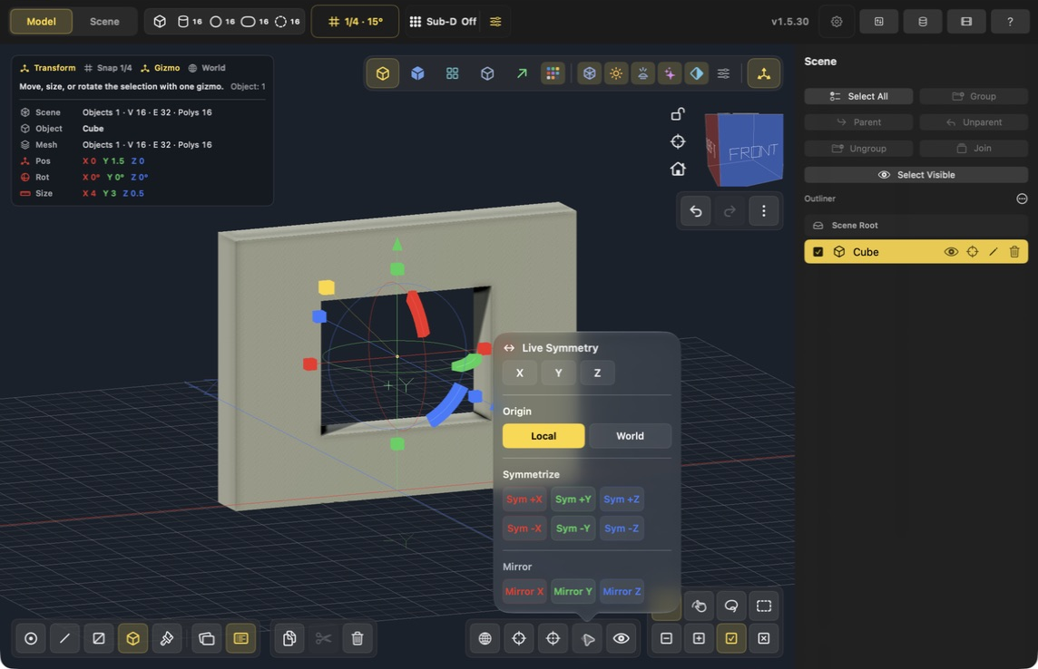
Current Mac controls. The screenshot has Origin set to Local; no symmetry operation has been applied to the wall.
Set Origin → Local for the local-axis examples below. World instead uses the scene world origin; check this setting before applying a mirror or symmetry operation.
Mirror X/Y/Z mirrors the selected geometry across the specified local axis. Check the object's origin and local axes to understand where the mirrored geometry goes.
Sym +X / Sym -X chooses which side to keep, then reconstructs the other side symmetrically across local X. The Y and Z variants work the same way. Choose the sign for the side containing the detail you want to preserve; the opposite side is replaced.
Live Symmetry mirrors supported edits as you work. It is useful while building both sides together. See symmetry and repeated parts.
Brush painting versus material assignment
Brush paints a stroke directly on the texture using Brush Size. It is useful for markings, scratches, and small color details.
Face and Object paint scopes assign the chosen material to an entire surface or object. Choosing Face scope does not mean painting in grid-sized blocks.
UVs describe where surfaces lie on the texture. They matter for where brush details land and whether surfaces share texture space. A solid material assignment does not require a hand-authored UV layout.
A tool is missing or nothing happens
Check selection and troubleshooting. The most common causes are the wrong selection mode, no component selected after switching modes, or another tool still waiting for Apply/Done or Cancel.